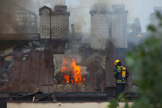
Fire is a common disaster that threatens people's lives and is prone to significant economic losses, with electrical issues being the main cause of fires. Large shopping malls, hotels, public buildings, intelligent buildings, petrochemicals, and other places often have a large number of electrical equipment distributed. These equipment types are diverse and widely distributed, and some devices have long working hours and heavy loads, which can easily cause electrical safety problems. In addition, aging of equipment and circuits can lead to increased contact resistance at the connection points due to oxidation, dust accumulation, and other factors, resulting in high local temperature rise. These electrical problems are extremely prone to fire.
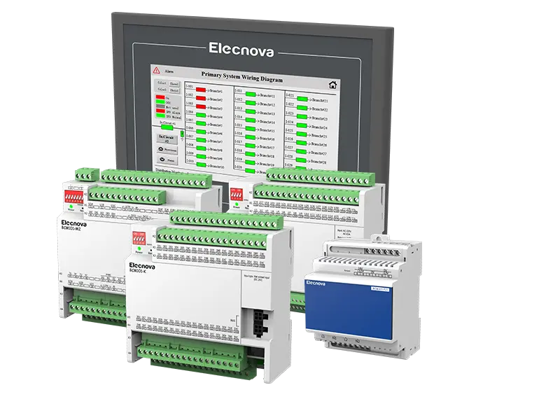
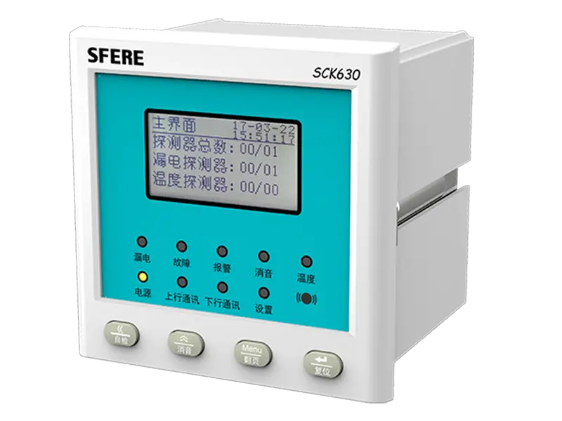
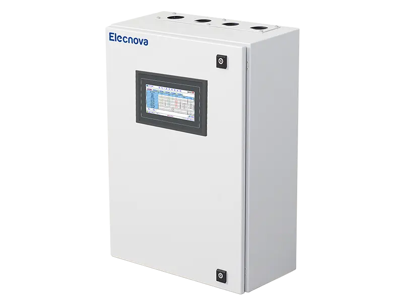
The SCK680-B/P electrical fire monitoring system consists of a monitoring host, residual current detectors, and temperature detectors, mainly used for monitoring and displaying parameters such as residual current and temperature in low-voltage distribution systems; According to the set protection threshold, make corresponding alarm prompts and protection actions; At the same time, remote networking monitoring can be achieved through RS485 or Ethernet to improve the safety of the entire electrical fire prevention system and eliminate potential electrical fires in their early stages.
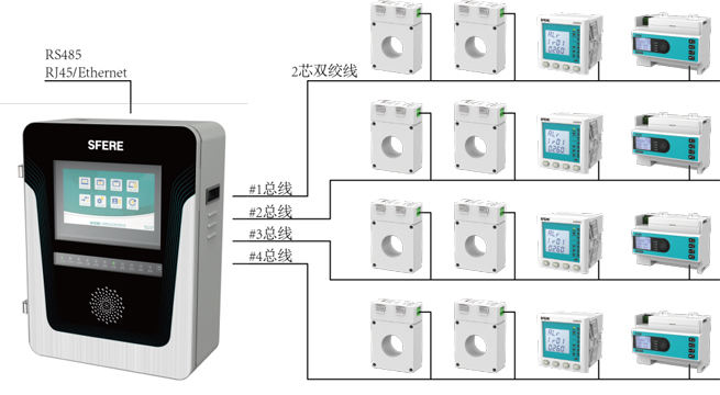
The SCK680-B/P electrical fire monitoring system adopts a three-layer distributed design of equipment layer, communication layer, and management layer, achieving decentralized control and centralized management. Regional multi-level monitoring equipment can be cascaded for monitoring of medium and large areas, achieving unified operation and setting, and displaying and alarming in different regions. A single monitoring device is used to achieve an integrated monitoring system for small and medium-sized areas. The detector signals in each installation area are uniformly sent to the monitoring equipment for centralized processing, display, alarm, and management. The system has a high cost-effectiveness.
Operational Principle
The monitoring host collects and converts signals from the front-end detector, and outputs sound and light information such as alarms, faults, and indications on the LCD touch screen, bright LED lights, and buzzers. By operating on the touch screen, the monitoring host is programmed and information is queried. At the same time, the integrated control module of the monitoring host controls various switch inputs and relay outputs. The switch power supply is responsible for the internal power supply, control, and status output of the entire device. The internal circuit is mainly composed of the main power supply circuit and the backup power circuit. While the main power is working, it charges the backup power. When the battery is fully charged, it automatically switches to a floating charge state to offset the self discharge of the battery and ensure the capacity of the battery during power supply. The monitoring equipment and detectors use a fire protection non-polar two bus communication, with each of the four buses capable of connecting 252 detectors. The total monitoring capacity can reach 1008 detectors.
System Characteristics
The monitoring host adopts a 10 inch industrial grade LCD touch screen
Non polarized two wire bus (power supply+communication), supporting any branch wiring
Circuit wiring using 1.5mm ² Twisted pair cables can achieve a transmission distance of 1500 meters
Secondary password setting function for easy maintenance and management
The detector supports automatic or manual encoding
Large capacity historical record storage function, with a storage capacity of up to 10000 pieces of information
Equipped with communication ports such as RS485 and Ethernet, facilitating the transmission and storage of various data
The function of real-time online query of temperature, humidity and other data information monitored by sensors
With real-time printing function, various types of information stored by the printing controller can be set according to actual needs
System Functions and Parameters
1. Real time monitoring
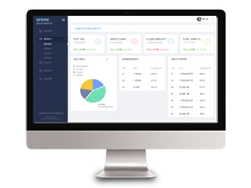
The system monitors the residual current and temperature values of each circuit in real time, and displays detailed circuit name and number content as well as various functional buttons on the main interface.
2. Alarm settings and prompts
The system supports remote setting of residual current and temperature alarm values, as well as various circuit information and status. When an alarm occurs in the circuit, the system emits an audible and visual alarm signal, and at the same time, the interface emits a significant color change, automatically recording detailed sequence of events. The number of event records is ≥ 60000, making it easy to trace.
3. Alarm and fault records
The system is equipped with a dedicated historical database that provides historical alarm records and historical fault records. Users can access, query, and print them at any time through the report interface. Users with advanced permissions or above can delete records one by one or all.
4. Alarm printing
The monitoring equipment is equipped with a micro printer, which can automatically/manually print alarm and fault information. Support setting the interface to automatically print information when an alarm/fault occurs.
5. Historical data trend curve
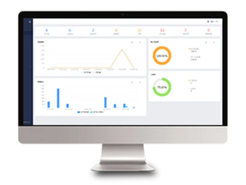
The system supports curve based querying of residual current and temperature data stored in history, and the query time interval and circuit can be dynamically set. The interface can reflect in real-time the changes in residual current or temperature during any given time period.
6. Status information display
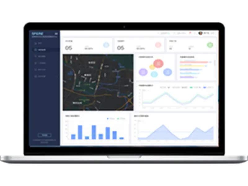
The system can display various current status information in real time (power supply status, equipment fault status, alarm status, and the working status of all communication devices) synchronously with the monitoring device indicator lights.
7. System fault self check
The monitoring equipment displays the real-time operation status of various internal functional modules and has fault self diagnosis function. At the same time, it displays the cause of the fault in real-time on the system interface and judges the communication status of detectors in various areas in real time, intelligently self checking the faults of the entire system.
8. User classification management
The system is divided into three levels of permission management, and different operations require corresponding permission levels to operate, in order to prevent misoperation and illegal entry.
9. System operation information
The system has an independent information window that records all operational information of the device after self startup, facilitating comprehensive judgment of the current status of the operating system.
10. Communication methods
Fire protection two bus method: pulse 24V non-polar two bus, dedicated communication protocol to achieve alarm interruption reporting, transmission distance ≤ 1.5km. RS485 bus mode: Modbus RTU communication protocol, half duplex mode, transmission distance of 1.2km (communication transmission distance can be extended through repeaters).
11. Working power supply
Main power supply: AC220V 50Hz (with a range of 85% to 110% allowed); Backup power supply: In case of low voltage or power outage of the main power supply, maintain the working time of the monitoring equipment for ≥ 4 hours.


