English
JIANGSU SFERE ELECTRIC CO., LTD.
EN

FAQ

Do you provide samples? Is it free or extra?

You need to pay for the sample and cover the freight as well.

Are you trading company or manufacturer ?

We are factory located in Jiangyin Jiangsu Province.

Does your company provide customized manufacturing?

We provide OEM/ODM service to our customers. Our experienced R&D team will give our customer solution in a high efficiency way.

How long is your delivery time?

3-5 working days for the items were in stock, 15-21days for the items out of stock.

What is your terms of payment?

Order amount less than $3000, 100% paid before shipment, order amount more than $3000,30% as deposit, 70% before shipment, or by negotiated for the both parties.

Instrument

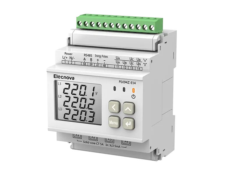
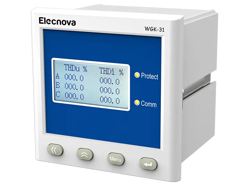
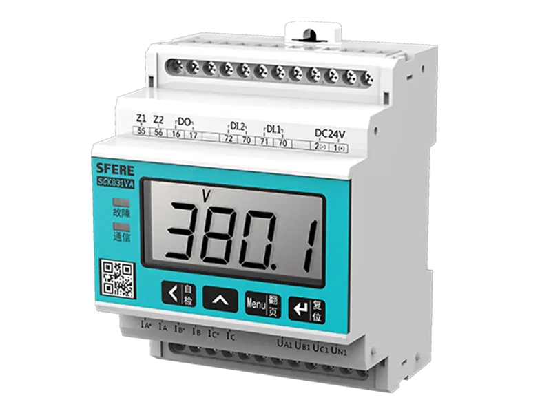
1. The instrument does not display after being powered on Possible reason: Auxiliary power supply not added to the instrument panel Solution: Use a multimeter to measure whether there is a corresponding working voltage on the auxiliary power terminals (1 and 2) of the instrument; Is the connection of the auxiliary power supply reliable.


2. Flashing after instrument is powered on

Possible cause: The power supply voltage exceeds the operating range of the instrument, causing protection of the instrument power supply; Signal input exceeds 120% of rated value

Solution: Disconnect the auxiliary power supply; Test whether the auxiliary power supply exceeds the range marked on the instrument; Test whether the input signal exceeds 120% of the rated value; Test whether the ambient temperature exceeds the upper limit of the usage environment temperature; Turn on the auxiliary power again.


3. The instrument displays garbled code after being powered on

Possible cause: The instrument panel is subject to significant interference

Solution: Disconnect the auxiliary power supply and power it on again;


4. Inaccurate display

Possible cause: Incorrect transformer ratio setting and mismatched parameters

Solution: Check whether the transformation ratio set by the instrument is consistent with that of PT and CT; Whether the rated values of voltage and current are consistent;


5. No response to signal addition

Possible reason: The signal was not added to the instrument panel

Solution: Test whether the instrument wiring terminals have signals and whether the terminal connections are reliable.


6. Three phase instrument missing phase

Possible reason: The signal was not added to the instrument panel, and the settings did not match

Solution: Test whether there is a signal at the wiring terminal of the instrument and whether the terminal connection is reliable; Connect the normally displayed phase signal line to the corresponding terminal of the missing phase to verify whether there is a problem with the instrument or peripheral circuit; Check if the wiring method of the instrument settings is consistent with the on-site wiring method.


7. Inaccurate electricity metering

Possible reasons: Incorrect transformer ratio and incorrect phase sequence of voltage and current

Solution: Check whether the transformation ratio set by the instrument is consistent with that of PT and CT; Check if the phase sequence of voltage and current is correct; In the case of a load, the power display of the instrument can be used to check whether there is a negative sign indicating the single-phase power. If there is a negative sign indicating, it is likely that the input and output lines of the corresponding phase current are reversed.


8. Analog output inaccurate

Possible reason: Analog output range and project correspondence are incorrect

Solution: Confirm the correspondence between the upper and lower limits of the analog output range; Confirm whether the electrical parameters corresponding to the analog output are correct, such as U, I, P, Q, etc., to ensure that the testing equipment is functioning properly. If using a PLC, ensure that the wiring settings for the analog input of the PLC are correct.


9. Communication abnormalities

1) The instrument has no feedback data

Firstly, ensure that the communication settings of the instrument, such as slave address, baud rate, verification method, etc., are consistent with the requirements of the upper computer; If there are multiple instruments on site without data feedback, check whether the connection of the field communication bus is accurate and reliable, and whether the RS485 converter is normal. If there is only a single or a few instrument communication abnormalities, the corresponding communication lines should also be checked. The address of the slave machine for exchanging abnormal and normal instruments can be modified to test, eliminate or confirm software problems on the upper computer, or test, eliminate or confirm instrument faults by exchanging the installation location of abnormal and normal instruments.

2) Inaccurate instrument feedback data

The instrument communication data includes primary power grid data (float type) and secondary power grid data (int/long type). Please carefully read the instructions on data storage addresses and formats in the communication address table, and ensure that they are converted according to the corresponding data formats. ModScan32 and other software can be used to test instrument communication.

3) Communication indicator status information

During the communication testing process, when the instrument receives data, the instrument communication indicator will flash and prompt.

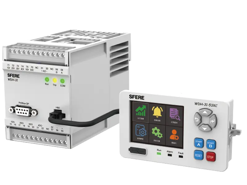
Motor Protector

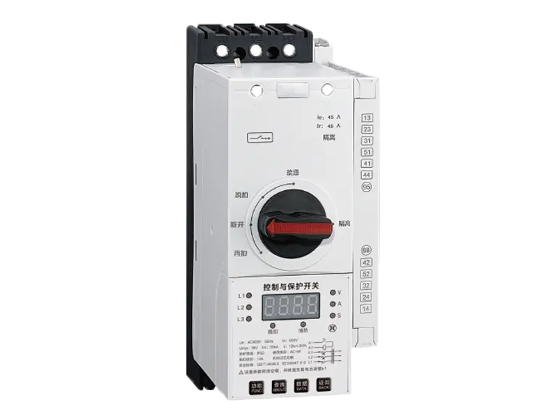
1. After power on, the main operation indicator light of the motor protection controller remains on, but the display module is not working properly

Possible cause: Poor contact of the dedicated DB9 connection wire connecting the controller body and display module (or broken wire due to bending)

Solution: After powering off, plug and unplug again, then tighten the DB9 connection cable or replace it with a new DB9 connection cable.


2. Abnormal contactor action during no-load test control circuit

When debugging the control circuit with no load, when the controller receives a start command from the display module button or DI terminal, the contactor is immediately released after being powered on and closed for 2 seconds, and cannot maintain a closed state; After the corresponding display module's "Start Interface" progress bar displays for 2 seconds, returning to the "Start Ready" interface may result in relay tampering. Possible reason: In addition to the "protection mode", in other control methods, the controller will detect the main circuit current to determine whether the startup is normal; If a start command is received, the main relay controlling the contactor circuit is closed, and the contactor is energized and closed. If the main circuit current does not reach 10% or more of the rated current after 2 seconds, it is considered that the motor is not running, and the relay is disconnected, and the contactor is released after losing power.

Solution (choose any one):

1) Enter the parameter setting interface for no-load debugging. In the "Controller Parameter Configuration" ->"Operation Mode" option, change "Operation" to "Test". After the change, the controller will not track the main circuit current, and all protection functions will not be activated. However, the control logic is working normally. In this state, you can debug whether the control circuit under no-load conditions is correct. After debugging correctly, please change the "running mode" back to "running".
2) On load debugging


3. The motor starts and stops normally, but the measurement parameters are incorrect. The motor protection controller may malfunction or refuse to operate

In the "Operation Data" interface of the display module, it appears that the three-phase current display is 0%; One phase current shows 0%, while the other two phases are normal; The three-phase current display is not 0, but the value differs significantly from the actual current; The voltage and current are correct, but the power and power factor are incorrect.

Possible reasons:

1) The built-in transformer plug of the controller is not reliably connected to the main body of the controller;

2) Incorrect setting of motor rated current and CT ratio;

3) The current specification of the controller does not match the motor circuit;

4) Wrong voltage and current phase sequence connection

Solution: Check if the built-in transformer is reliably connected to the controller; Correctly set the rated current and CT ratio of the motor (when using an external transformer); Check the voltage and current phase sequence.

Power Quality Products

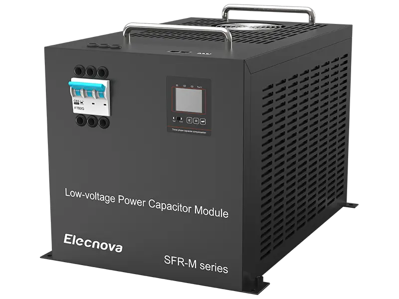
Common faults and solutions of SFR-L/M

1.1 Power on Strong Input

The internal composite switch of the smart capacitor is disconnected when it leaves the factory, but due to vibration and other reasons during transportation, it may cause the composite switch to change from disconnected to closed. At this time, only connect to the power grid that can withstand the current of this module, and let the module power on and reset.

1.2 External indicator lights turn on when the module is powered on, and turn off when the module is powered off

Confirm the module type, whether it is co compensation or sub compensation. If it is co compensation, connect the external indicator light to the common terminal Ub; If it is a partial compensation, the external indicator light common terminal is connected to Un.

1.3 When put into operation, the indicator light flashes

After the capacitor is put in and then cut off, it needs to be discharged for a period of time. If it is put in again at this time, there will be a phenomenon of not being able to put on (the C1 and C2 indicator lights will flash), and the switching delay of the control host will be extended (it is recommended to be ≥ 30 seconds).

1.4 Controller not switching

The main reasons why controllers do not switch are as follows

① Is the CT ratio parameter set correctly? This parameter is crucial

② The user's on-site load is relatively small and the current is not high. After the load starts, the controller will automatically switch on and off.

1.5 Controller Display Signal Protection

The main reason for controller signal protection is that the sampled signal is not collected by the controller, resulting in signal protection.

1.6 There are always 1 or 2 groups that cannot be manually networked by the controller

The main reason is that the address of the intelligent reactive power compensation module is duplicated, and the controller can only recognize non duplicated addresses. It only needs to be changed to non duplicated addresses between 1 and 32.