Enterprise overview
Dongfeng Honda Automotive Parts Co., Ltd. mainly produces key components for Honda series sedan engines and chassis, and is an important production base for Honda passenger cars in China. The products involve camshafts, connecting rods, crankshafts, cylinder liners, front and rear steering knuckles, fork arms, front and rear brake discs, etc., mainly used in Honda series train models produced by Dongfeng Honda Automobile Co., Ltd., GAC Honda Automobile Co., Ltd., Honda Motor (China) Co., Ltd., and overseas companies.

Overall project situation
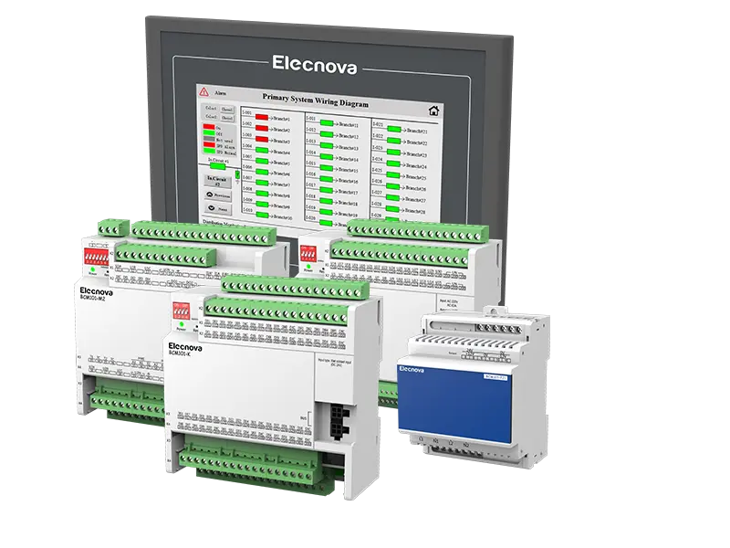
This project is the intelligent monitoring and energy management system project for the comprehensive station building of Dongfeng Honda Automotive Parts Co., Ltd. The project consists of three parts: intelligent power monitoring system, energy management system, and electrical fire monitoring system. These three parts are three relatively independent systems, each with its own independent hardware and running software. The intelligent power monitoring system, energy management system, and electrical fire monitoring system can achieve data sharing through network connection. The intelligent monitoring and energy management system host is installed in the monitoring duty room of the energy station building.
The equipment for this procurement bidding is the software and hardware equipment included in the intelligent power monitoring system; The software and hardware equipment included in the energy management system; The electrical fire monitoring system includes software and hardware equipment, and is responsible for connecting, installing, and debugging with the equipment to be monitored. When necessary, interface components, measuring devices, etc. of the system should be installed on other devices to be monitored, and responsible for the joint debugging with the intelligent monitoring and energy management system.
Project scope
This plan includes an intelligent power monitoring system, an electrical fire monitoring system, an intelligent control system for air compressors, and an automatic water supply control system. The system includes software and hardware equipment for power parameter measurement, factory water measurement, factory gas measurement, natural gas measurement, and electrical fire monitoring, and is responsible for connecting, installing, and debugging with the equipment to be monitored. The external interface of the system provides real-time data for the energy management system.
Design basis
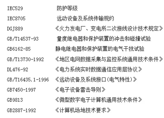
Configure according to the drawing situation
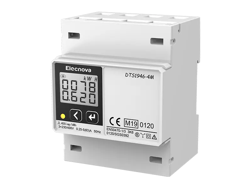
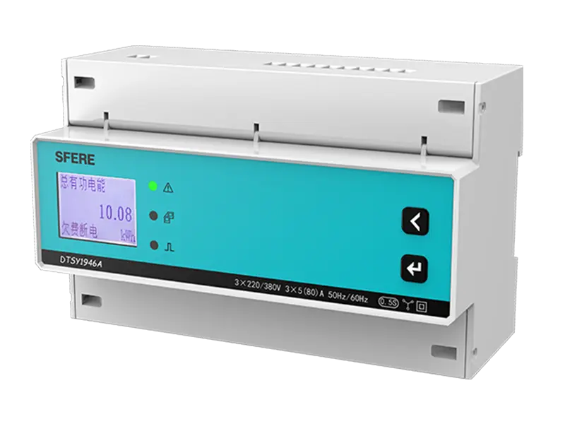
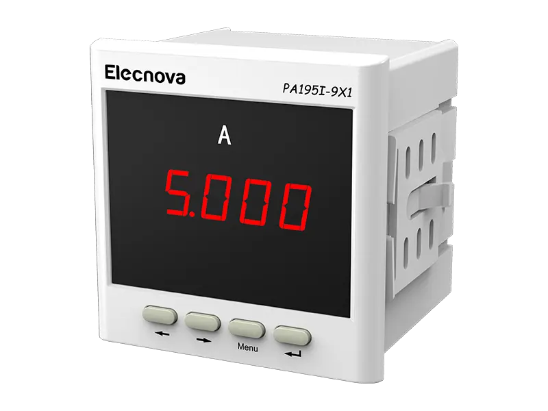
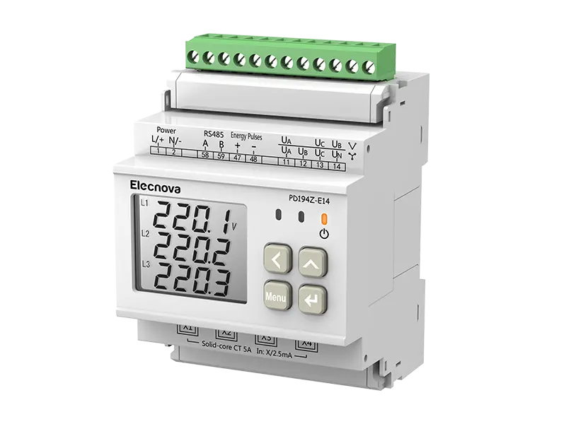
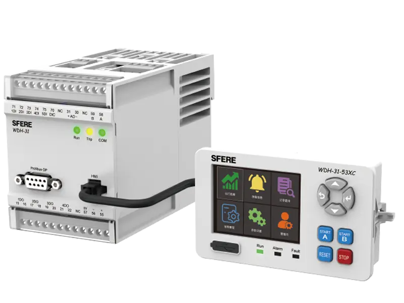
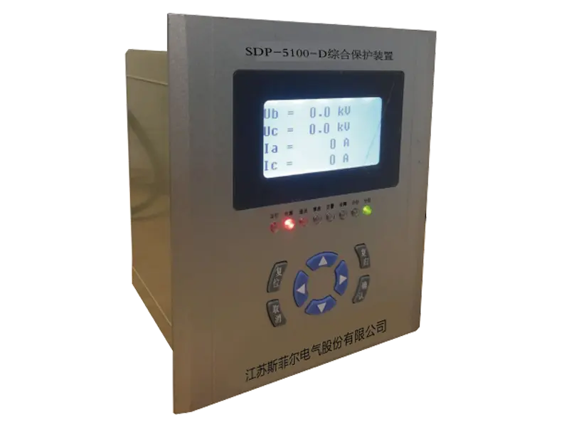
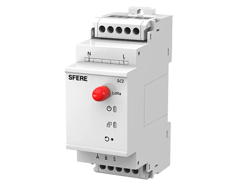
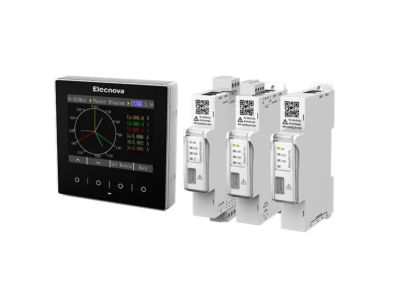
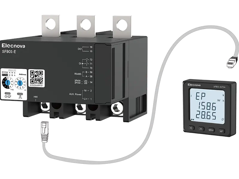
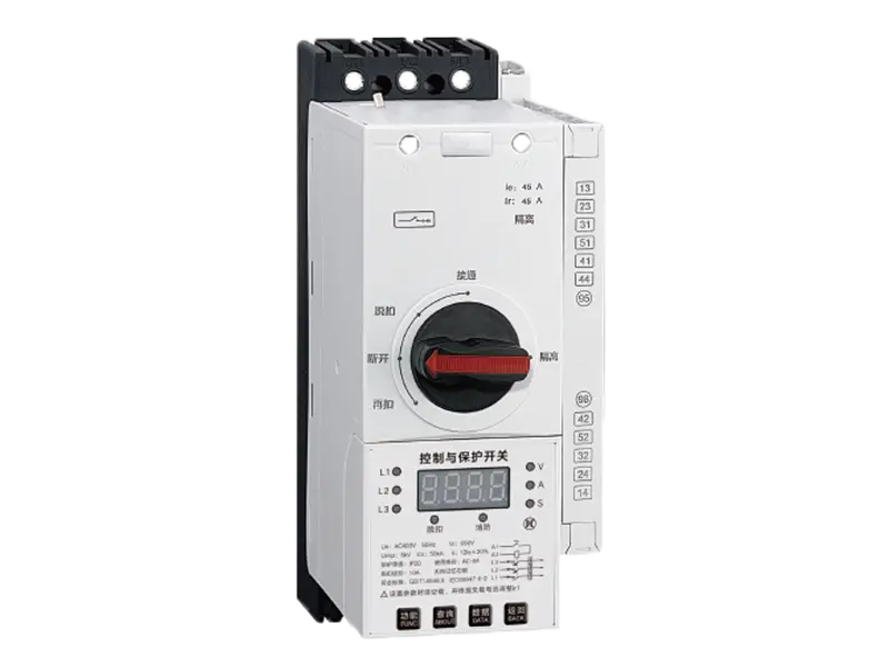
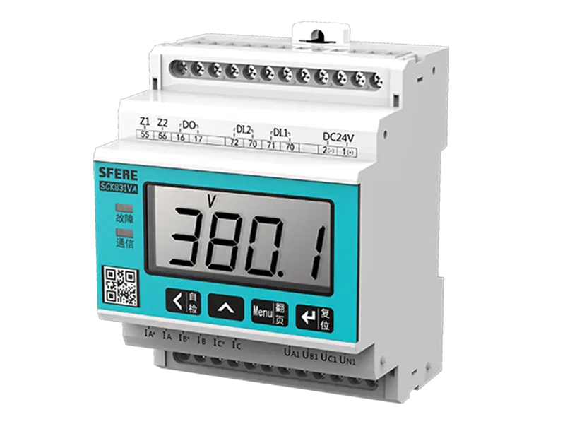
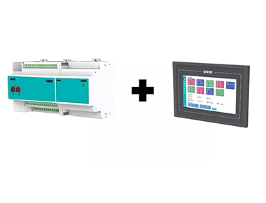
Install multifunctional power instrument PD194Z-9HY and comprehensive protector on the circuit of the distribution cabinets in each distribution room where power monitoring instruments need to be installed on the drawings, monitor the current and voltage of individual circuits in real time, and then connect them to the communication management machine in each distribution room.
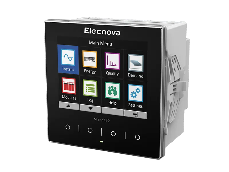
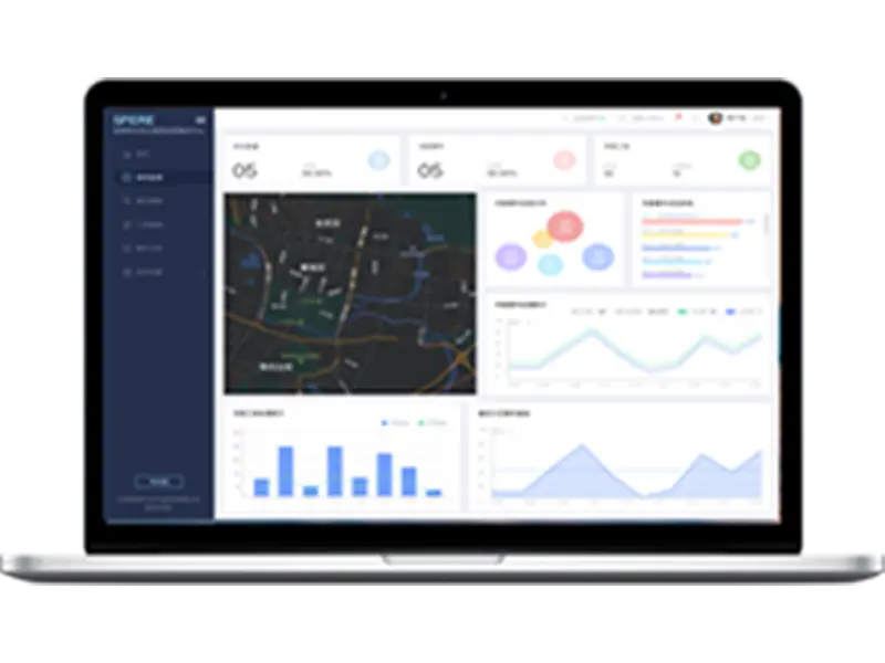
After the completion of the system, the communication management machines in each distribution room are pulled to the main control room of the main building through optical converters, and all monitoring data is transmitted to the SFERE3000 power monitoring system.
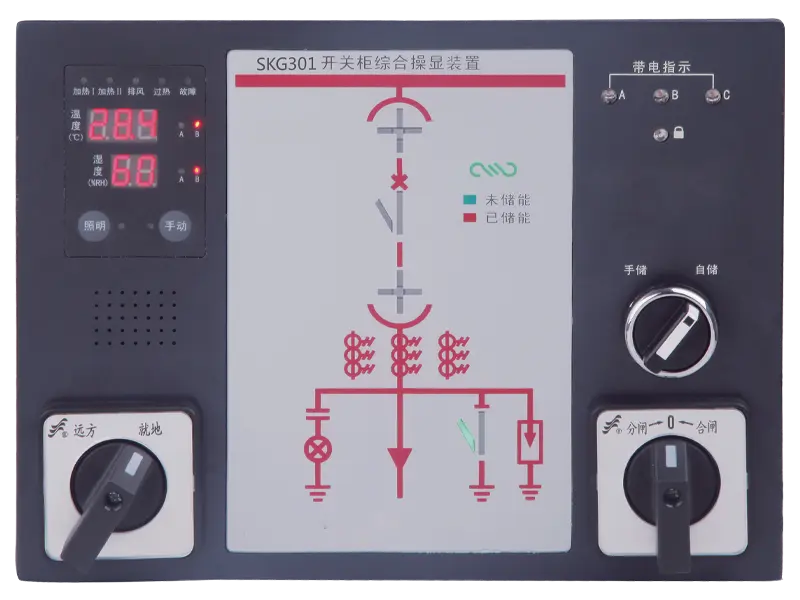
Other devices with digital communication interfaces, such as transformer temperature control equipment, DC equipment, analog screens, etc., require data to be uploaded to the backend computer for remote monitoring or control.
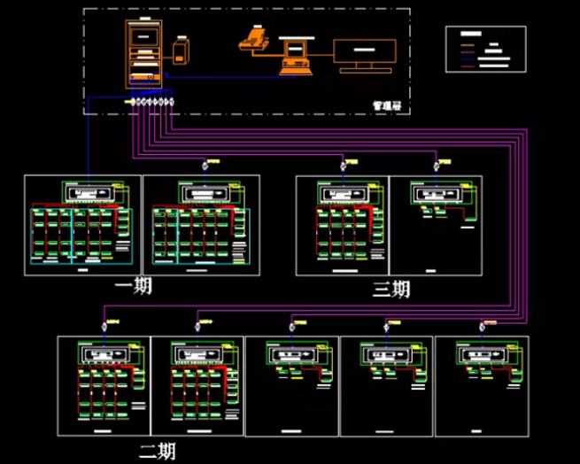
Network topology diagram
The overall network acquisition structure of this system is based on the fiber optic TP/IP network communication between each distribution room and the main control room of the main building, to complete centralized data collection and processing. The network is divided into upper layer network and lower layer network. The upper layer network refers to the Ethernet (or fiber optic Ethernet) from each substation to the control center. Industrial grade fiber optic transceivers are used for photoelectric conversion between optical fibers and various management devices.
The underlying network consists of RS485 communication cables between instruments, protection equipment, etc., which are laid using dedicated twisted pair cables. As the communication management machine is configured in their respective sub stations, RS485 transmission distance is all within the sub stations, and there will be no long-distance signal interference or attenuation issues. The on-site equipment layer of the network mainly includes measuring instruments, protective devices, etc., which are installed locally in the corresponding switchgear, have local operation functions, and are not affected by remote computer start stop. This system is divided into three layers from bottom to top: device terminal layer, network communication layer, and system management layer.
Implement functions
It can automatically collect and intelligently manage the electrical energy information of various metering points in the high-voltage and low-voltage distribution rooms of the entire plant, ensuring that the distribution network operates in a safe, reliable, high-quality, and efficient optimal state, achieving remote measurement, control, and management of the distribution network, and meeting the needs of electricity safety, energy management, and energy conservation and consumption reduction.
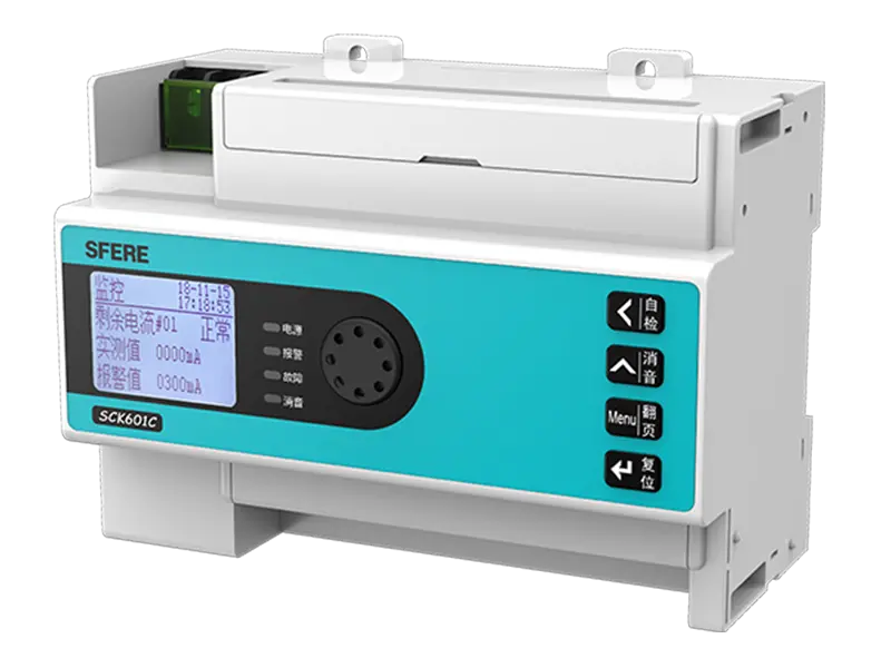
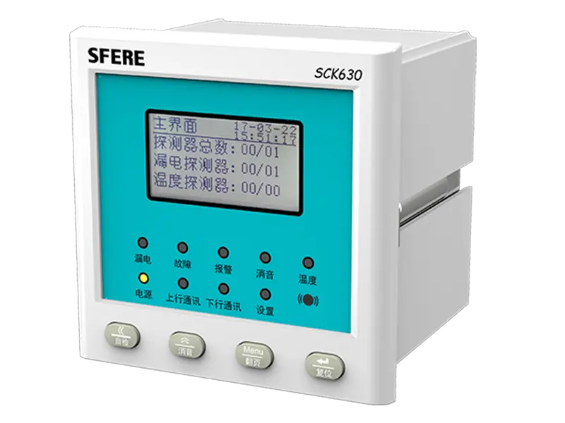
By monitoring parameters such as residual current and load current in the circuit, alarm and monitoring of the protected electrical circuit can be achieved, and it can be uploaded to the fire monitoring system for centralized control and management. When the relevant parameters in the circuit are abnormal, the monitoring equipment emits an audible and visual alarm, indicating the alarm location. At the same time, the on-site detector emits an audible and visual alarm and control signal to remind users to investigate or replace hidden circuits, reducing the risk of fire caused by electrical reasons.


