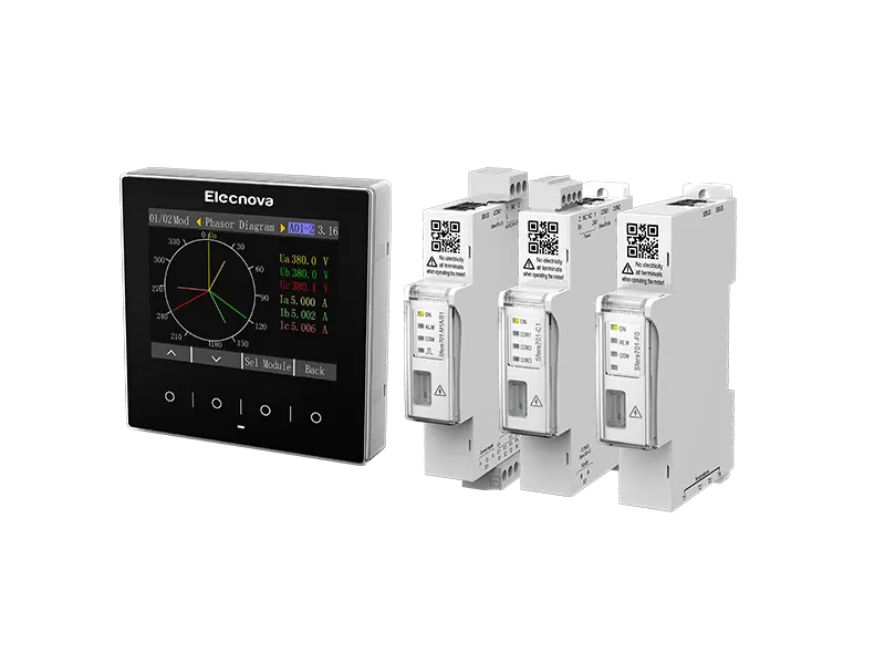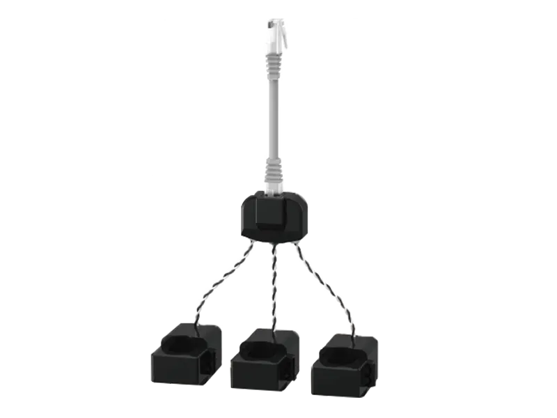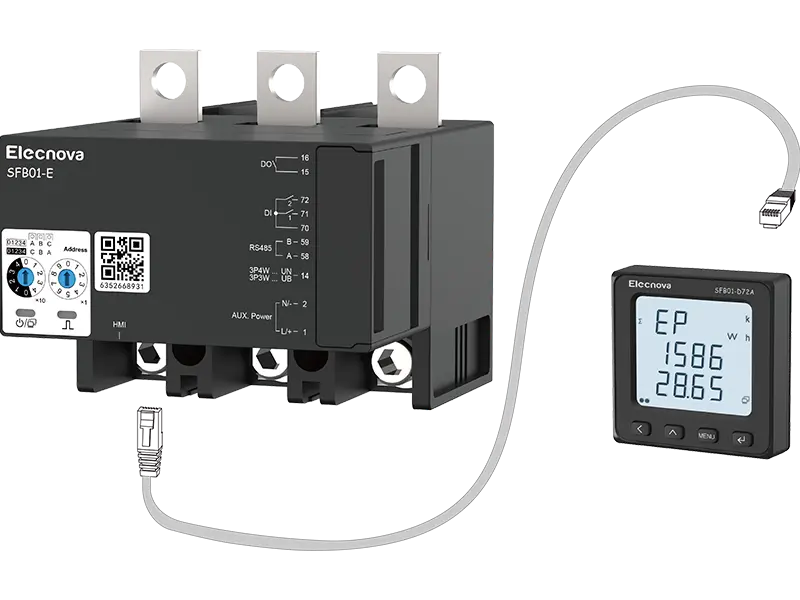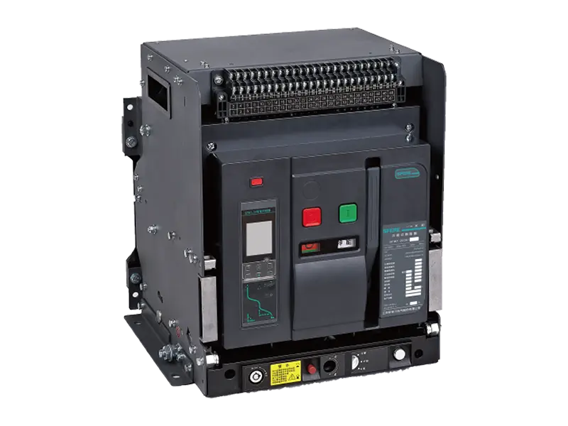
Part 1 Overall Plan
1.1 Project Overview
The Jiangyin Hailan Innovation Building is a frame structure with 55 floors above ground, 3 floors underground, and an additional 4 floors of podiums, with a total construction area of approximately 225000 square meters. Design an energy management system as a whole, collect and summarize data from water meters and power meters on each floor, and generate settlement reports; Install multifunctional electrical fire detectors on each power supply circuit to achieve measurement and control of circuit parameters and status, and simultaneously collect and analyze the leakage situation of the power supply circuit in real time, and give real-time alarms for circuits that exceed the standard.

1.2 Design specifications
IEC61000-4-30:2003 "Electromagnetic compatibility testing and measurement techniques - Methods for measuring power quality"
IEC61000-4-7:2002 "Electromagnetic compatibility testing and measurement techniques - Guidelines for the measurement and use of harmonics and mutual harmonics - Connection of power systems and equipment"
GB/T14537-93 "Impact and collision tests for measuring relays and protective devices"
GB6162-85 "Electrical Interference Test for Electrostatic Relays and Protection Devices"
GB/T13730-1992 General technical requirements for data acquisition and monitoring systems in regional power grids
GB/T16435.1-1996 Telecontrol Equipment and System Interface (Electrical Characteristics)
GB7450-1997 Guidelines for Lightning strikes on Electronic Equipment
GB9813 General Technical Conditions for Micro Digital Electronic Computers
GB2887-1992 Technical Requirements for Computer Field
GB/T 19862-2005 General Requirements for Power Quality Testing Equipment
GB6833.1-6833.10-1987 "Electromagnetic Compatibility Test Specification for Electronic Measuring Instruments"
GB14287-2005 Electrical Fire Monitoring System
DL476-92 Real time Data Communication Application Layer Protocol for Power Systems
DL/T448-2000 Technical Management Regulations for Electric Energy Measurement Devices
DL/T5202-2004 Technical Specification for Design of Electric Energy Measurement Systems
DL/T645-2007 Multifunctional Energy Meter Communication Protocol
DL/T614-2007 Multifunctional Energy Meter
DL/T5202-2004 Technical Specification for Design of Electric Energy Measurement Systems
DL/T645-2007 Multifunctional Energy Meter Communication Protocol
DL/T614-2007 Multifunctional Energy Meter
1.3 System composition
This plan adopts a three-layer structure, which includes: monitoring management layer, network layer, and on-site measurement and control layer.
The monitoring management layer consists of two monitoring hosts, which simultaneously realize functions of power monitoring, energy management, and electrical fire monitoring. The backbone of the network layer adopts a fiber optic ring network topology structure to ensure the reliability of information transmission. The on-site measurement and control layer mainly consists of electrical fire detectors, power metering instruments, and water meters. The system forms an energy management system with on-site monitoring, data transmission, and centralized monitoring.
1. Monitoring management layer: The entire energy management system is equipped with two sets of monitoring hosts: one is the SCK680-G256 electrical fire monitoring equipment installed in the distribution duty room on the negative first floor, and the other is the monitoring host installed in the fire control center on the first floor. The two hosts achieve the same functions of power monitoring, alarm, automatic energy meter reading, and automatic water meter reading. And set multi-level user permissions to achieve different levels of operation for different accounts. Two sets of monitoring equipment are respectively connected to the network layer through the communication cabinets in the weak current room on the negative first floor of the main building and podium.
2. Network layer: A network composed of various communication devices and media, enabling data exchange between the system management layer and on-site measurement and control layer devices. The main network of this project adopts a fiber optic ring network, and the downstream measurement and control layer equipment is connected using an RS-485 bus structure. The communication equipment includes a communication management machine, an industrial ring network switch, a fiber optic transceiver, as well as optical cables, communication cables, etc.
3. On site measurement and control layer: composed of electrical fire detectors, power measuring instruments, and water meters installed on site, realizing functions such as measurement, monitoring, communication, and control. Based on the measurement, control, and communication functions of the on-site measurement and control layer equipment, the system can achieve functions such as telemetry, remote signaling, remote control, and remote adjustment.
1.4 System Function Introduction
1.4.1 Power monitoring function
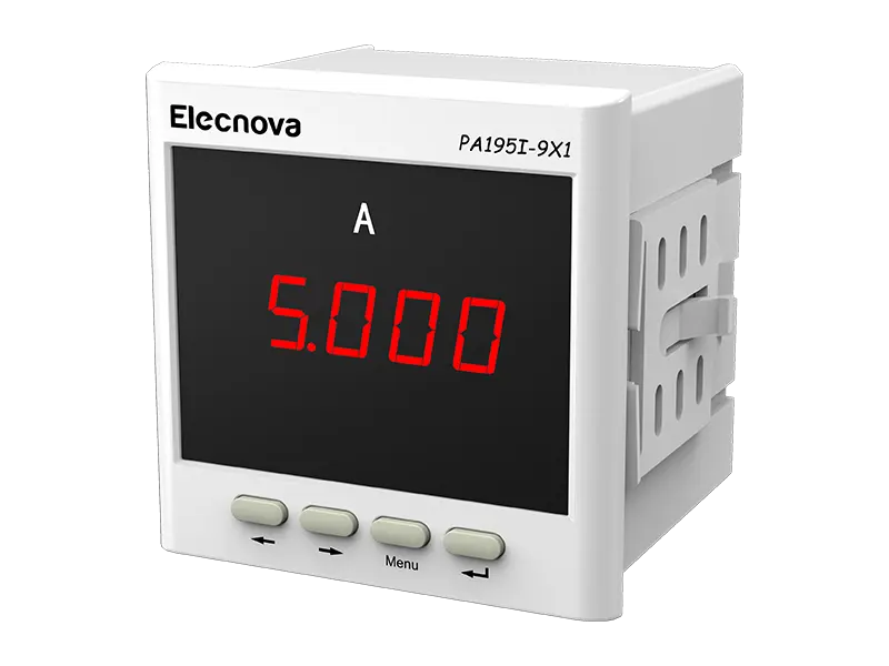
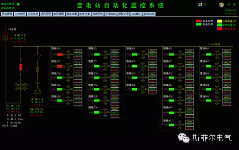
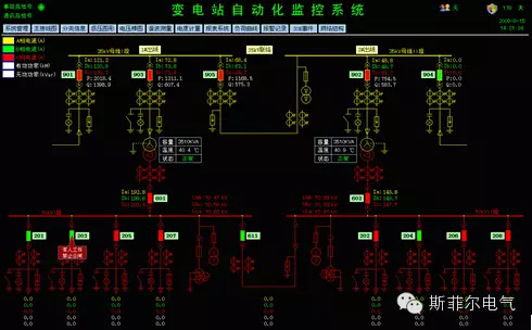
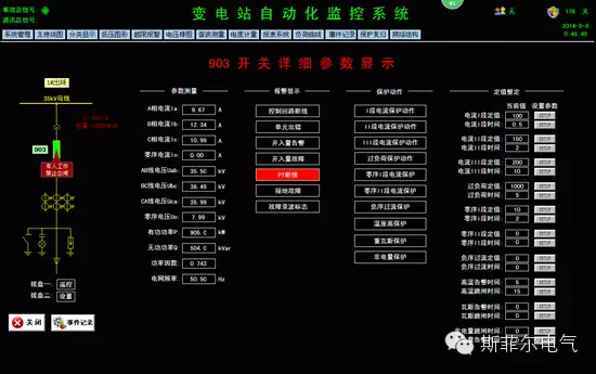
Telemetry: supports the display mode of primary diagrams for power transformation and distribution, and real-time collection and display of electrical parameters such as current, voltage, power, and power factor in high and low voltage circuits.



1.4.2 Interconnection with High Voltage Systems
System interconnection, when other types of automation systems provide standard OPC interfaces or standard protocol forwarding functions to achieve data sharing, the system can be interconnected with other automation systems.
At the request of the customer, the system needs to be interconnected with the high-voltage system, and the high-voltage system needs to provide an Ethernet interface with Modbus TCP or 104 protocol or standard OPC interface
1.4.3 Remote meter reading function
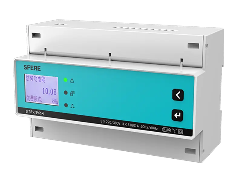
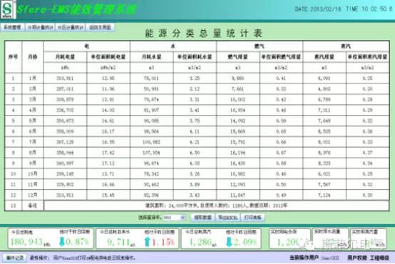
Automatically read metering devices such as water meters and electricity meters between floors, store and process the collected data, and generate various statistical reports, such as daily reports, monthly reports, quarterly reports, annual reports, compound rate reports, etc., to facilitate users to grasp energy consumption status and settle expenses.
1.4.4 Electrical fire monitoring function
The system monitors the residual current and temperature values of each circuit in real-time, and displays detailed circuit name and number content on the main interface. It supports remote setting of residual current and temperature alarm values, as well as various circuit information and status.
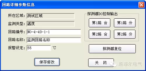
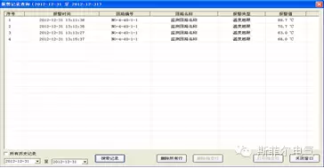
When an alarm occurs in the circuit, the system emits an audible and visual alarm signal, and at the same time, the interface emits a significant color change, and a detailed sequence of event records is automatically recorded. The retention period of the event records is ≥ 24 months, making it easy to trace.

1.5 Network Structure
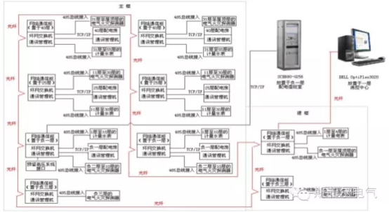
The overall network of this plan is laid out according to the ring network structure, and the redundant ring network structure can ensure high reliability of the network and convenience of fiber optic laying.
All network acquisition nodes are configured according to the distribution of strong electric wells, and each network acquisition node is composed of communication management machine, industrial ring network switch, network communication cabinet, etc. This plan sets up a total of 9 network acquisition nodes in the weak point well next to the strong current well on the negative third floor, negative first floor, 25th floor, and 40th floor of the main building, as well as the negative first floor and negative third floor of the podium building. These 9 network nodes are connected by fiber optic ring network. The actual layout of network equipment on each floor is as follows.
Part of the network in the podium building is equipped with one communication management machine and one ring network switch at the network acquisition node on the negative first floor of the podium building. The power metering instruments on the 1st to 4th floors of the podium building, as well as the electrical fire detectors on the 1st to 4th floors, roof level, and negative first floor of the podium building, are all connected to this communication management machine; Install one S3100C8E2 communication management machine and ring network switch at the network acquisition node on the negative third floor of the podium, connect to the electrical fire detectors on the negative second and negative third floors, and achieve centralized data collection and network forwarding transmission.
The above ground network of the main building consists of two strong electric wells on the 55th floor. The plan is to set up four network acquisition nodes on the 25th and 40th floors of the main building. The electrical fire detectors and water meters on floors 11 to 30 are connected to the acquisition nodes on the 25th floor. The electrical fire detectors and water meters on floors 31 to the roof are connected to the acquisition nodes on the 40th floor. A total of four communication management machines, four ring network switches, and four network communication cabinets are installed.
In addition, an additional communication management machine will be added to the 25th and 40th floor distribution rooms to connect electrical fire detectors and instruments for all circuits in the corresponding distribution rooms. These two communication management machines are laid out through TCP/IP network to the switch of the network acquisition node on the corresponding floor.
The underground network of the main building is equipped with one communication management machine for each network acquisition node on the negative first and third floors. The negative first floor communication management machine is connected to the electrical fire detectors in each distribution box on the negative first and second floors. In addition, the negative first floor communication management machine is also connected to the electrical fire detectors and water meters on floors 1-10; The communication management machine on the negative third floor is connected to the electrical fire detectors in each distribution box on this floor.
At the same time, a communication management machine is installed in the main substation on the negative first floor for the connection of all electrical fire detectors and monitoring instruments in the substation. Finally, the communication management machine is connected to the weak current well switch on the negative first floor through TCP/IP network, achieving the overall system networking.
1.6 Selection of Monitoring Management Equipment
The two monitoring servers of the monitoring management layer run simultaneously to achieve data collection, monitoring, data processing and storage of the entire system. When either server fails, it does not affect the normal operation of the other, ensuring the reliability and integrity of the entire system.
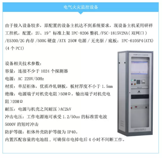
1.6.1 SCK680-G256 monitoring host
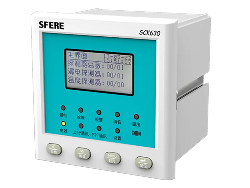
SCK680-G256 electrical fire monitoring equipment, equipped with RS485 and TCP/IP networking channels, can connect no less than 1024 detectors for centralized monitoring. It fully meets the GB14287.1-2005 standard for monitoring parameters such as faults and alarm signals. At the same time, this system has passed the 3C mandatory certification of the National Fire Electronic Product Quality Supervision and Inspection Center.
The monitoring device supports one click start and shutdown operations through a key. The device has two TCP/IP network interfaces, which can directly connect to the on-site detector in network mode to read relevant data. At the same time, the operator can log in to the system with a password to dynamically modify the relevant circuit parameters of the system, alarm settings, and remote reset functions. The device is equipped with a built-in voice alarm and an embedded micro printer, which can provide sound and light alarms and print all system faults and alarm information.
1.6.2 Monitoring server
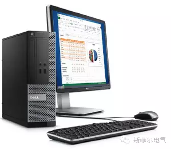
All monitoring servers located in the fire control center adopt server computers with large storage capacity and high-speed processing performance, and are also equipped with a printer for printing user reports.
1.6.3 Electrical fire detectors
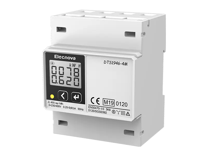
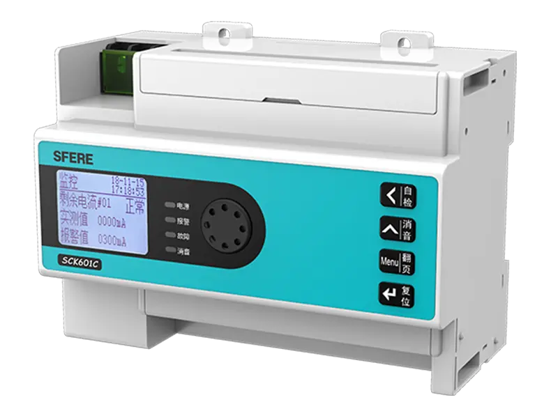
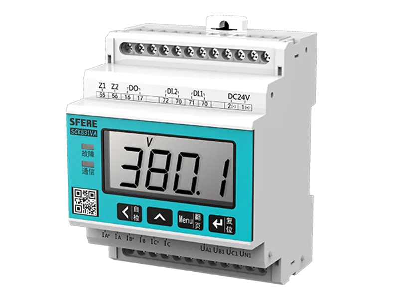
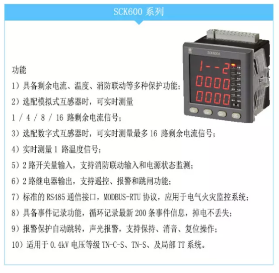
The electrical fire detector is installed in the local distribution cabinet and well distribution box to measure the residual current, temperature, and electrical parameters of each circuit. The SCK600 series detector is used in this project; Equipped with one residual current, three temperatures, and full power parameters and energy metering functions, enabling electrical fire monitoring, power monitoring, and energy metering functions to be simultaneously installed in some circuits with one device.
Part 2 System Functions
Power monitoring module functions
2.1 System operation monitoring
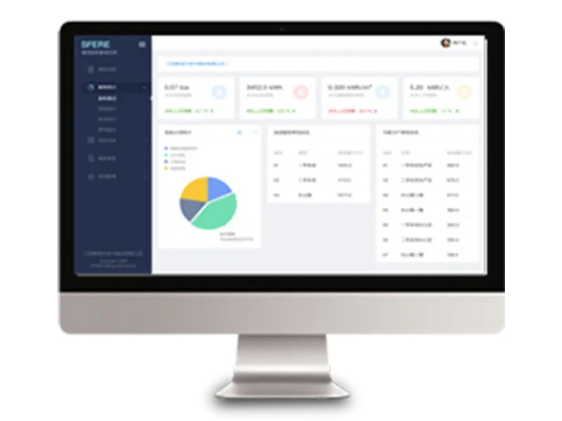
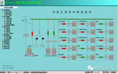
The system collects data from all on-site equipment through a round robin method. In the main interface of the system, according to the distribution system diagram, real-time collection and display of electrical parameters such as current, voltage, power, and power factor in the high and low voltage circuits. Equipped with various display colors to distinguish the opening and closing status display and provide sound and light alarm prompts.
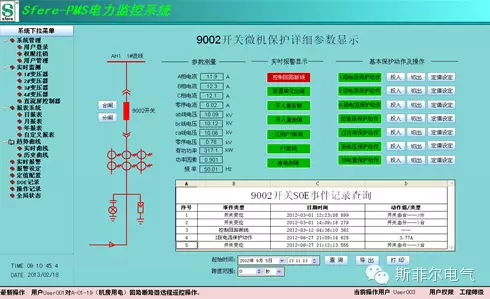
2.2 Remote control and parameter settings
Can achieve remote opening and closing control for specified circuits, set protection on/off, and adjust alarm protection parameters; And conduct event analysis and fault recording data analysis on the alarm or trip circuit, identify the cause of the alarm or trip, provide various alarm fault displays for operators, and prompt potential fault hazard reports for the system, providing effective guarantees for the safe operation of the system.
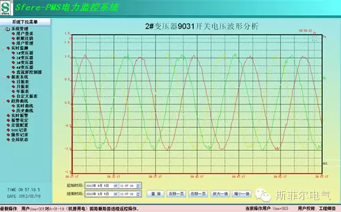
2.3 Load trend curve analysis
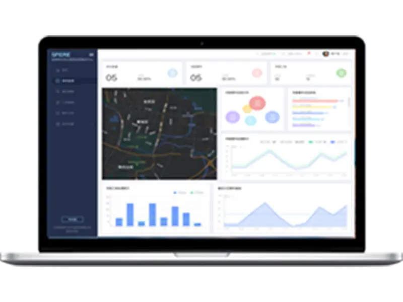
The trend curve system can continuously monitor the operating parameters of equipment in real-time, such as power load, waveform capture at the moment of fault occurrence, helping users dynamically analyze the historical changes of various data, and providing strong data basis for management personnel to predict the parameter changes and future trends of the power supply system during a certain period of time.
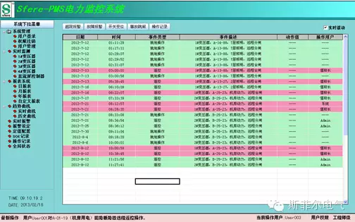
2.4 Event recording and inquiry
Real time monitoring of various status event information such as alarm status, trip status, switch displacement status of each circuit, issuing obvious sound and light alarms for alarm and trip monitoring events, and recording all events that occur in the system, in order to provide data support for detailed analysis by operators.
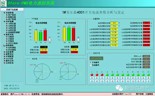
2.5 Graphical analysis management
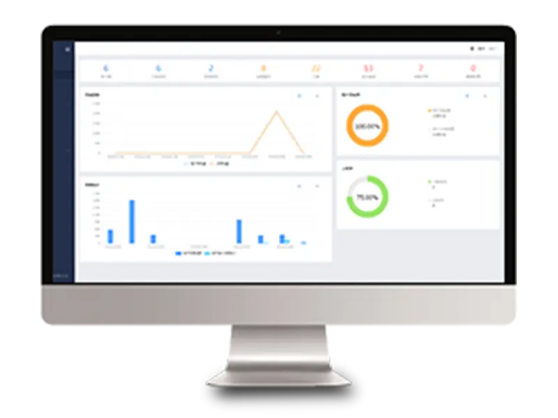
The system can generate various operational statistical dynamic image systems, such as voltage bar charts, pie charts, and phase angle charts, and can graphically analyze real-time changes in various power grid parameters (such as imbalance, phase angle, etc.); And it can set alarm and trip limits for sensitive power parameters that affect the normal operation of the system load, issue alarms in advance or automatically send trip output control to ensure the reliability of the system.
2.6 Real time data reporting
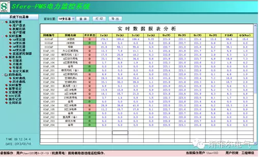
The real-time reporting system provides a unified table mode for real-time display of data and status for the operating system. It can dynamically compare and monitor various circuits in real time. The real-time reports support exporting data in Excel format, making it convenient for phase II processing.
2.7 Historical Data Report Query
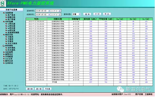
The historical report system can provide various historical data report queries, such as daily reports, quarterly reports, monthly reports, annual reports, etc. It can query various historical data such as current, voltage, power load, electricity metering, etc., generate various statistical data, and provide data support for user measurement statistics, internal consumption analysis, and other needs.
2.8 Third party device access
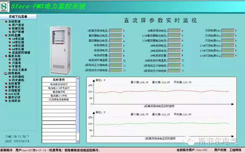
The system supports communication protocols for various serial ports and Ethernet buses, and can develop and design non-standard protocols at the bottom level to facilitate equipment access and integration, such as microcomputer protection devices, DC screen controllers, transformer temperature controllers, intelligent analog screens, reactive power compensation controllers, water and gas metering devices from various manufacturers, achieving centralized and unified monitoring.
2.9 System Interconnection
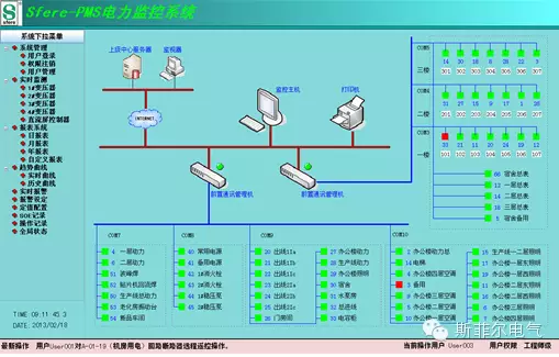
Provide standard OPC interfaces or standard protocol forwarding functions for other types of automation systems, achieve data uploading and sharing, and provide a unified scheduling interface for higher-level scheduling systems.
2.10 System Security
Multiple user levels and corresponding operation permissions can be set. Control operations have strict password protection requirements, and different operators are subject to different permission restrictions. When modifying alarm parameters, the system automatically verifies the operator's permissions and password. Only when operators with operating permissions enter the correct password, can they have the authority to modify the operation.
Electrical fire module function
2.11 Real time monitoring of residual current
The system monitors the residual current and temperature values of each circuit in real time, and displays detailed circuit name and number content as well as various functional buttons on the main interface.
2.12 Residual current alarm settings and prompts
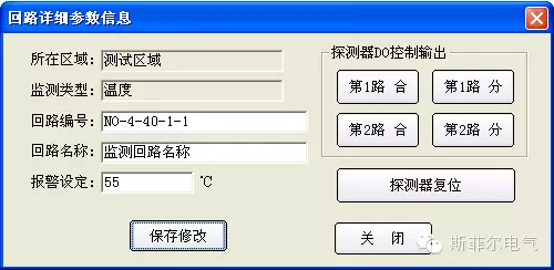
The system supports remote setting of residual current and temperature alarm values, as well as various circuit information and status. When an alarm occurs in the circuit, the system emits an audible and visual alarm signal, and at the same time, the interface emits a significant color change, and a detailed sequence of event records is automatically recorded. The retention period of the event records is ≥ 24 months, making it easy to trace.
2.13 Alarm and Fault Records
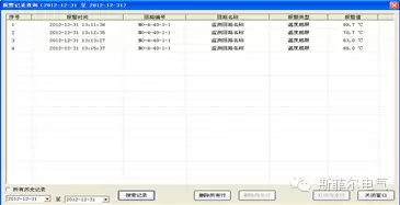
The system is equipped with a dedicated historical database that provides historical alarm records and historical fault records. Users can access, query, and print them at any time through the report interface. Users with advanced permissions or above can delete records one by one or all.

2.14 Alarm Printing
The monitoring equipment is equipped with a micro printer, which can automatically/manually print alarm and fault information. Support setting the interface to automatically print information when an alarm/fault occurs.
2.15 Historical trend curve of residual current data
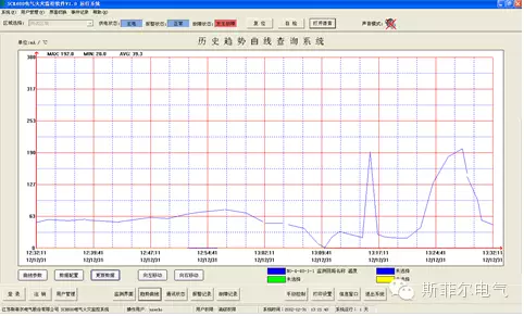
The system supports curve based querying of residual current and temperature data stored in history, and the query time interval and circuit can be dynamically set. The interface can reflect in real-time the range of residual current or temperature changes within any given time period.
2.16 Display of device status information
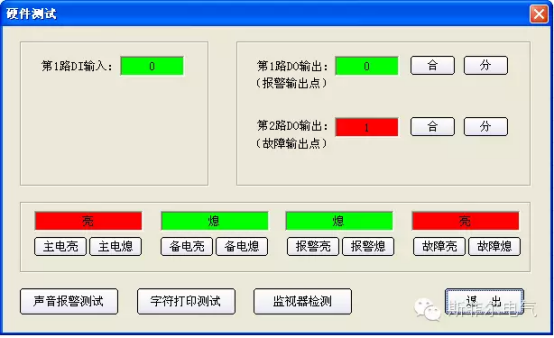
The system can display various current status information in real time (power supply status, equipment fault status, alarm status, and the working status of all communication devices) synchronously with the monitoring device indicator lights.
2.17 System Fault Self Test
The monitoring equipment displays the real-time operation status of various internal functional modules and has fault self diagnosis function. At the same time, it displays the cause of the fault in real-time on the system interface and judges the communication status of detectors in various areas in real time, intelligently self checking the faults of the entire system.
2.18 User Grading Management
The system is divided into three levels of permission management, and different operations require corresponding permission levels to operate, in order to prevent misoperation and illegal entry.
2.19 System operation information
The system has an independent information window that records all operational information of the device after self startup, facilitating comprehensive judgment of the current status of the operating system.
2.20 Technical performance indicators of power monitoring module
System capacity:>10000 points
System availability: ≥ 99.9%
Average server load rate: ≤ 20%
Average network load rate: ≤ 10%
Integrated measurement error within the station: ≤ 0.5%
Monitor screen call response time:<2 seconds
Dynamic data refresh:<3 seconds
Alarm occurrence to output:<2 seconds
Host database refresh:<1 second
Measurement voltage accuracy: ≤ 0.2%
Measurement current accuracy: ≤ 0.2%
Measurement accuracy of active power: ≤ 0.5%
Measurement accuracy of reactive power: ≤ 0.5%
Measurement frequency accuracy: ≤ 0.02Hz
Measurement accuracy of active power: ≤ 1%
Measurement accuracy of reactive power: ≤ 2%
Remote control resolution: ≤ 100 milliseconds
Control command to output time: ≤ 1 second
Remote signal displacement transmission time: ≤ 2 seconds
Event recording accuracy: ≥ 99.9%
Remote signal accuracy: ≥ 99.9%
Remote control accuracy: ≥ 99.9%
Real time data refresh time: ≤ 2 seconds
Mean time between system failures: 50000 hours


